Dismantling The Frame
Remove the fuel tank.
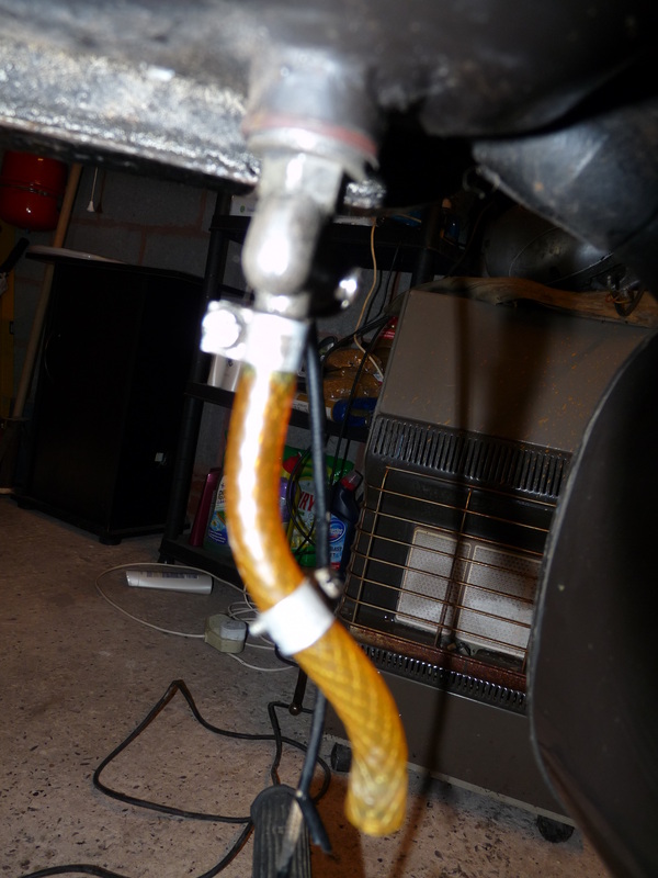
Firstly detach the fuel pipe by loosening the screw with a flat-headed screwdriver and sliding it off. Tighten the screw back up afterwards, place in a bag and label.
Firstly detach the fuel pipe by loosening the screw with a flat-headed screwdriver and sliding it off. Tighten the screw back up afterwards, place in a bag and label.
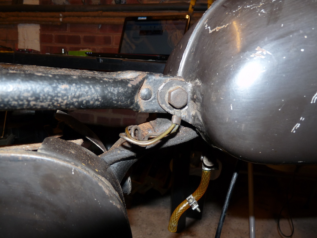
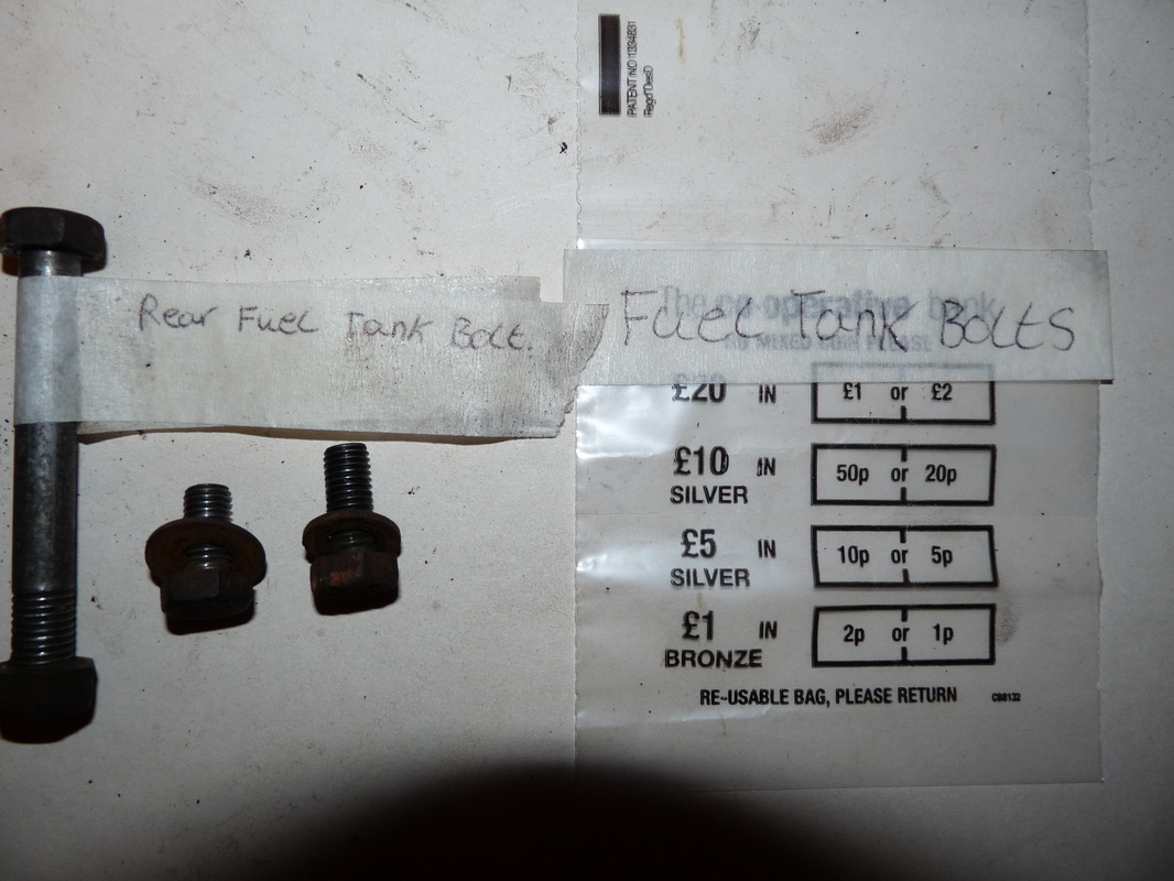
Then undo the bolt at the back of the fuel tank using a 15mm socket (SAE size 19/32).
Label the bolt with some masking tape, something like "rear fuel tank bolt", and put aside.
Label the bolt with some masking tape, something like "rear fuel tank bolt", and put aside.
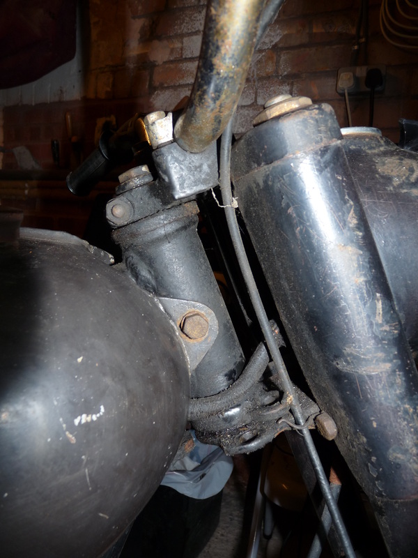
Next remove the two small bolts at the front of the fuel tank, one on either side.
Place all fuel tank bolts in a coin bag, label and out somewhere safe.
The fuel tank should now lift free from the frame.
Place all fuel tank bolts in a coin bag, label and out somewhere safe.
The fuel tank should now lift free from the frame.
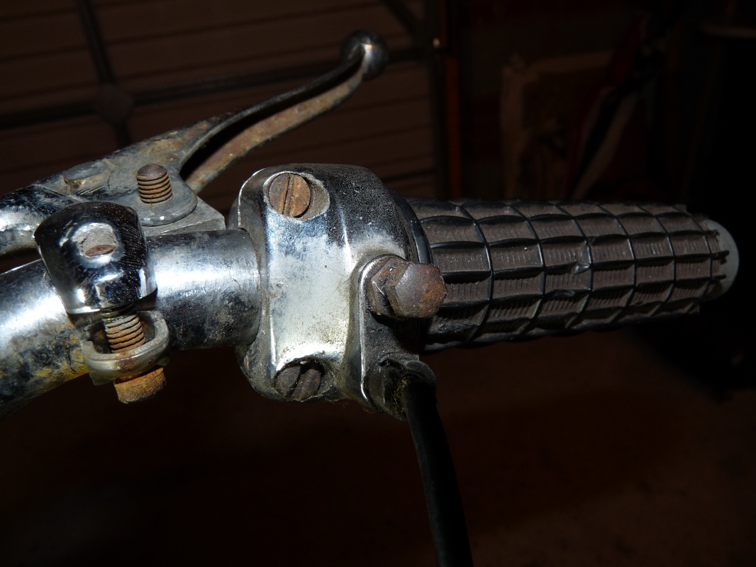
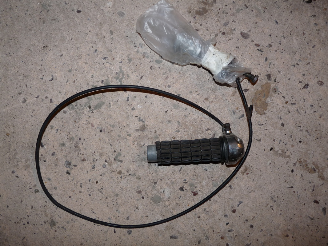
Now remove the throttle from the handle bars by undoing the two screws with a flat-headed screwdriver. The throttle should simple slide off. Place the whole assemble in a bag and label it.
While you're at it remove the front break and the horn/dipper switch from the handle bars and just leave them to dangle for the time being.
While you're at it remove the front break and the horn/dipper switch from the handle bars and just leave them to dangle for the time being.
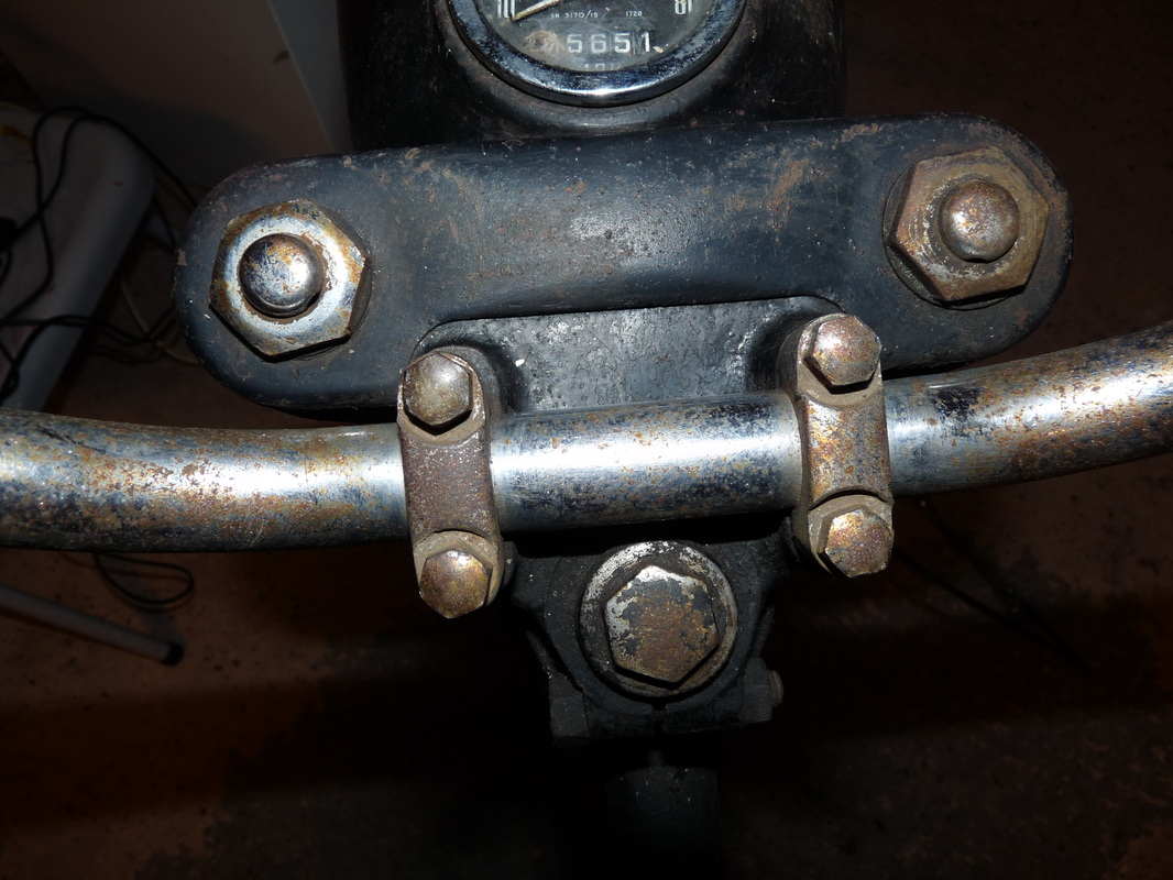
Next, using a 12mm socket (SAE size 15/32), undo the four bolts that hole the handle bars in place.
Put the four bolts and two brackets in a coin bag, label and put in a safe place.
Put the handle bars next to the fuel tank.
Put the four bolts and two brackets in a coin bag, label and put in a safe place.
Put the handle bars next to the fuel tank.
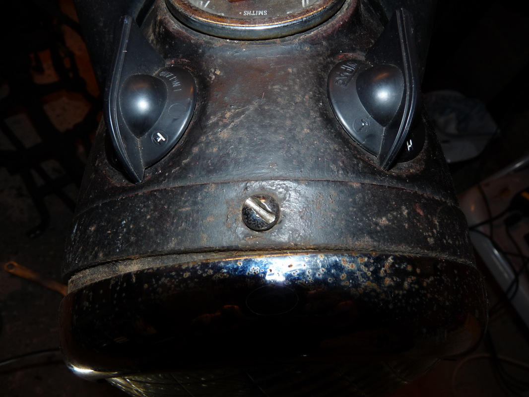
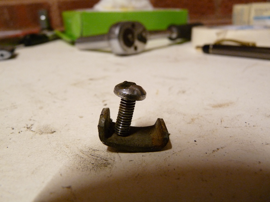
Now remove the screw at the top of the headlamp. You might hear a small bracket drop out, make sure you don't loose this.
Gently prise the headlamp off, be careful not to damage it.
Place the screw and the bracket in a coin bag, label and put somewhere safe.... I bet you wished you pinched more coin bags now.
Gently prise the headlamp off, be careful not to damage it.
Place the screw and the bracket in a coin bag, label and put somewhere safe.... I bet you wished you pinched more coin bags now.
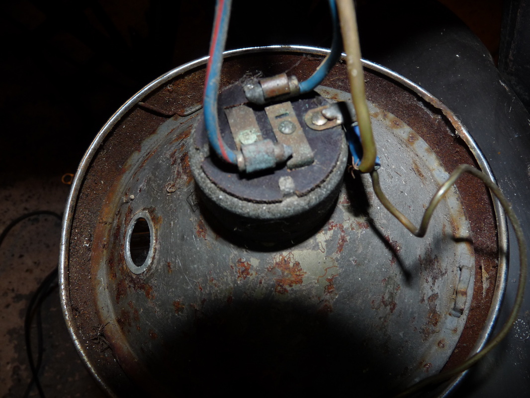
Slide the bullet connectors out of the back of the headlamp.
Put the headlamp somewhere safe for now.
Put the headlamp somewhere safe for now.
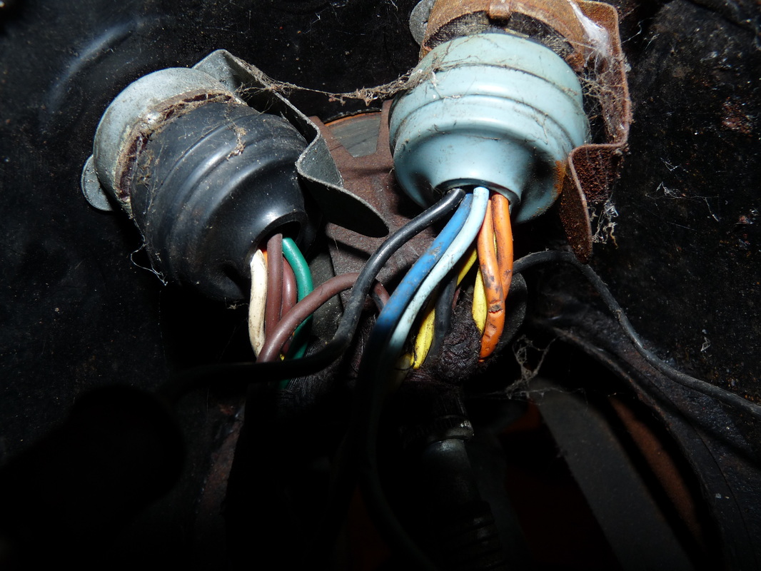
Next slide the plugs out from the back of both switches.
Slide all of the cables, including the horn/dipper switch, out through the back of the headlamp casing.
This was home to several spiders.
Slide all of the cables, including the horn/dipper switch, out through the back of the headlamp casing.
This was home to several spiders.
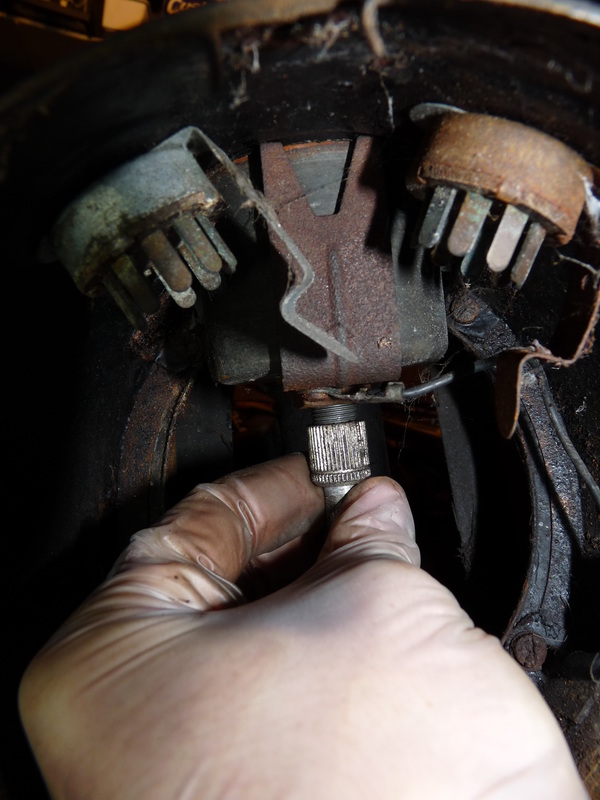
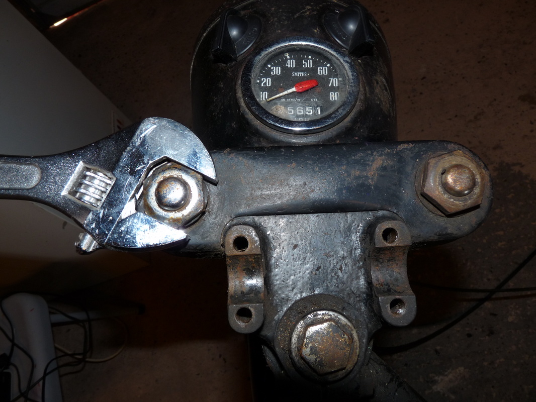
Unscrew the cable connected to the back of the speedometer.
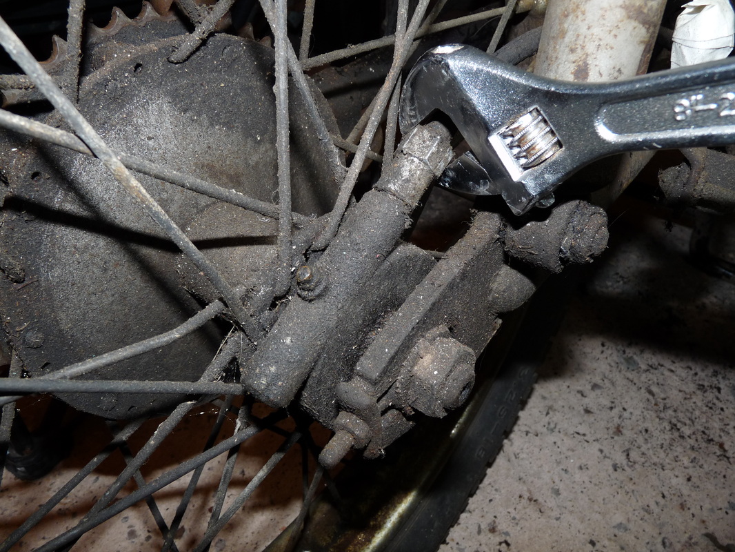
While you're at it, trace this wire to the back wheel and undo the nut holding it in place there.
The speedometer cable cannot be removed until the headlamp casing has.
While you're at it, trace this wire to the back wheel and undo the nut holding it in place there.
The speedometer cable cannot be removed until the headlamp casing has.
You may prefer to do the next part after dismantling the front wheel assembly.
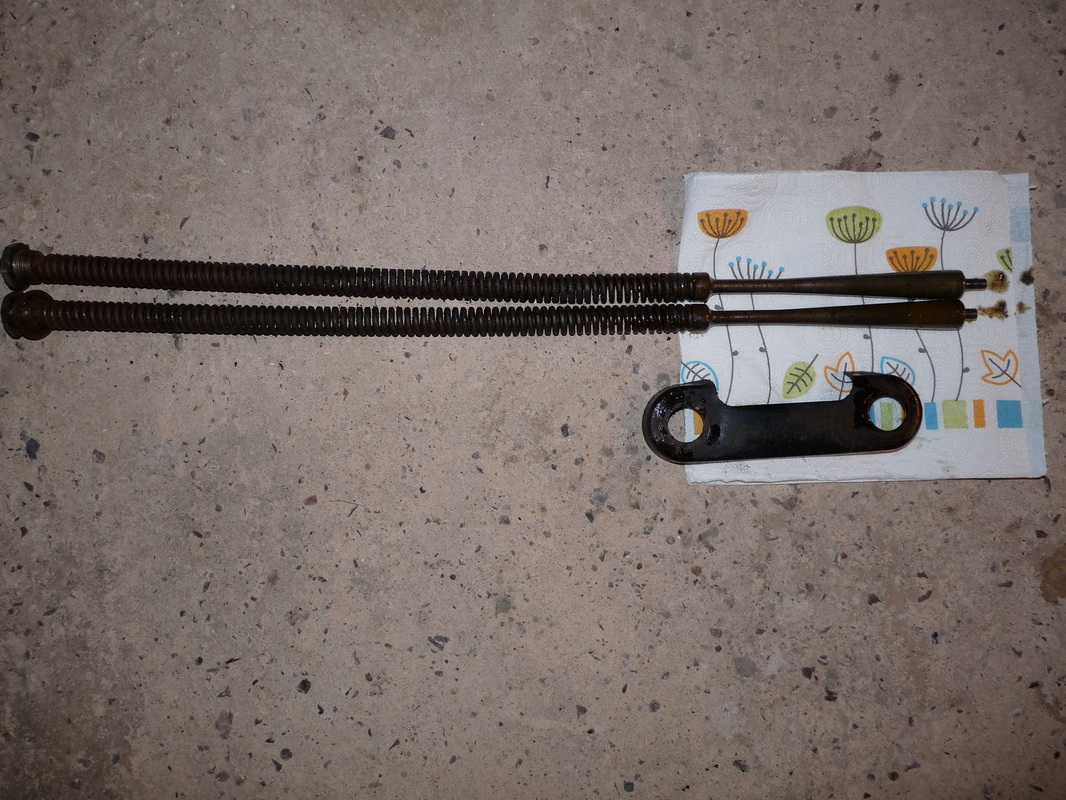
Undo the two nuts shown and take the springs out/ They will be quite oily so be sure to have some paper towels to hand. Place them and the bracket somewhere safe.
Undo the two nuts shown and take the springs out/ They will be quite oily so be sure to have some paper towels to hand. Place them and the bracket somewhere safe.
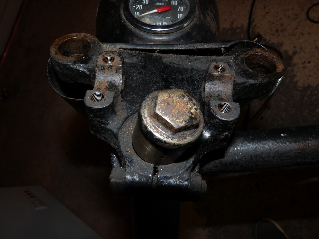
Using a 21mm socket (SAE 13/16) undo the final bolt and remove the top yoke. Label and place aside.
Do this next part very carefully. You may want to refer to the diagram on page 54 of "Haynes,BSA Bantam, 123cc-148cc-174cc. 1948 to 1971"
Take of the top cap (furthest right in the picture).
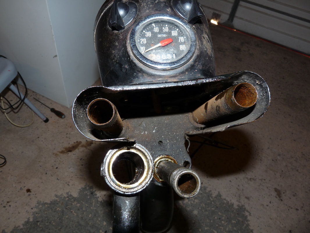
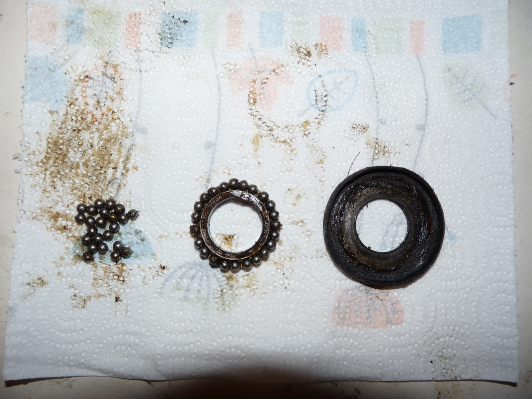
Slide out the bearing guide and the bearings (center in picture). Be sure to collect any that didn't come.
Now slowly lift up the frame of the bike and slide out the bottom yoke along with the front wheel assembly.
Collect all the bearings. There should be 46 in total, 23 for the top and 23 for the bottom.
Put these all in a coin bag and label it "yoke bearings". I would recommend double bagging these.
Roll the front wheel assembly somewhere safe for the moment.
Take of the top cap (furthest right in the picture).
Slide out the bearing guide and the bearings (center in picture). Be sure to collect any that didn't come.
Now slowly lift up the frame of the bike and slide out the bottom yoke along with the front wheel assembly.
Collect all the bearings. There should be 46 in total, 23 for the top and 23 for the bottom.
Put these all in a coin bag and label it "yoke bearings". I would recommend double bagging these.
Roll the front wheel assembly somewhere safe for the moment.
Now to finish removing the wiring harness.
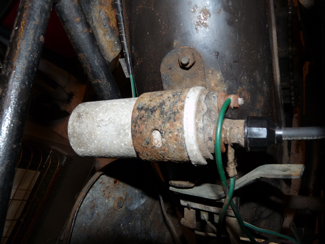
Start by disconnecting the spark plug cable from the ignition coil.
If you wiring harness is in good condition and you don't plan to replace it disconnect the other 2 wires from the ignition coil also. Otherwise just snip them off.
Start by disconnecting the spark plug cable from the ignition coil.
If you wiring harness is in good condition and you don't plan to replace it disconnect the other 2 wires from the ignition coil also. Otherwise just snip them off.
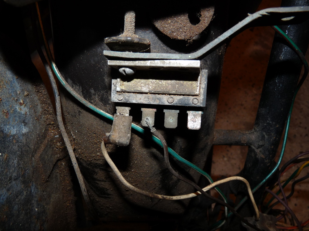
Disconnect all the wires at the rectifier.
While you're at it take the rectifier off of the rear mud guard along with the toolbox bracket.
You might as well dump the rectifier and replace it. Defiantly do this if you plan to change to 12 volts. Label the toolbox bracket and put it somewhere safe.
While you're at it take the rectifier off of the rear mud guard along with the toolbox bracket.
You might as well dump the rectifier and replace it. Defiantly do this if you plan to change to 12 volts. Label the toolbox bracket and put it somewhere safe.
Now round to the back on the bike.
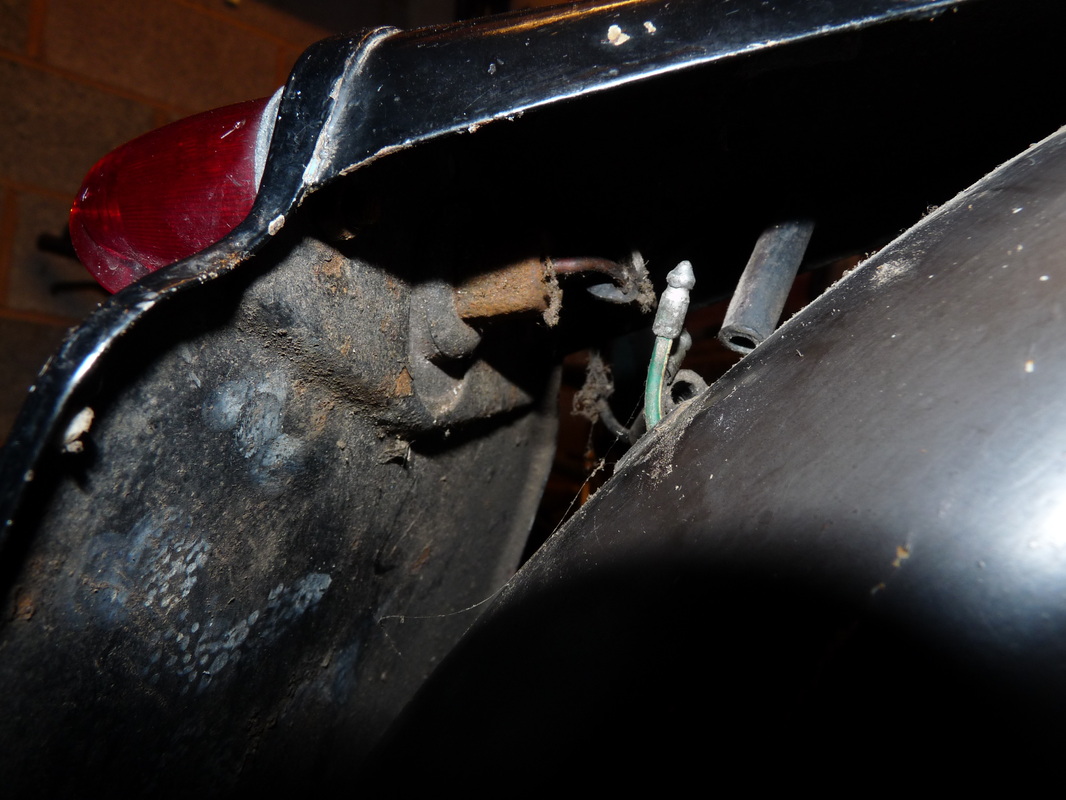
Disconnect the two bullet connectors for the break light. They are located just behind the number plate.
Thread the wires through the rear mud guard
Disconnect the two bullet connectors for the break light. They are located just behind the number plate.
Thread the wires through the rear mud guard
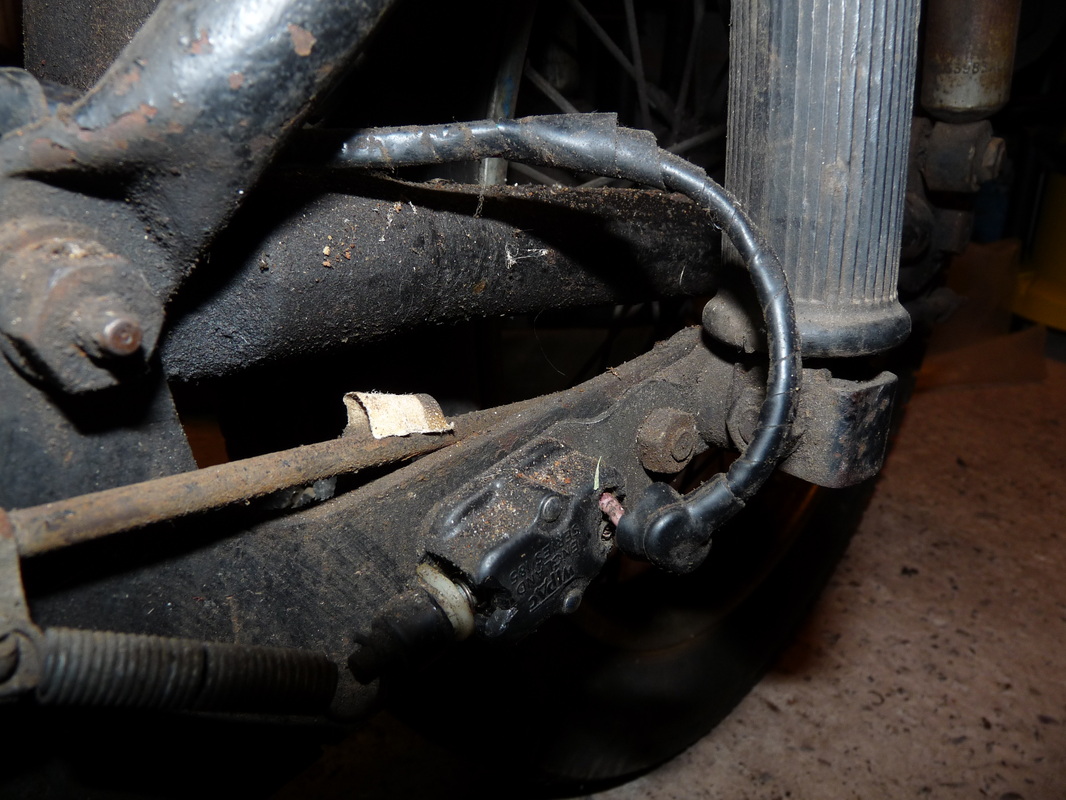
The very last thing to disconnect is the wire that connects to the rear break mechanism.
That's the wiring harness removed.
That's the wiring harness removed.
Now to remove the tool box. If you haven't done so already remove both side panels. As you can see from the "initial photos slideshow" this bike didn't come with the side panels attached. I'm also pretty sure that one of the side panels given to me is not from a D7 model.
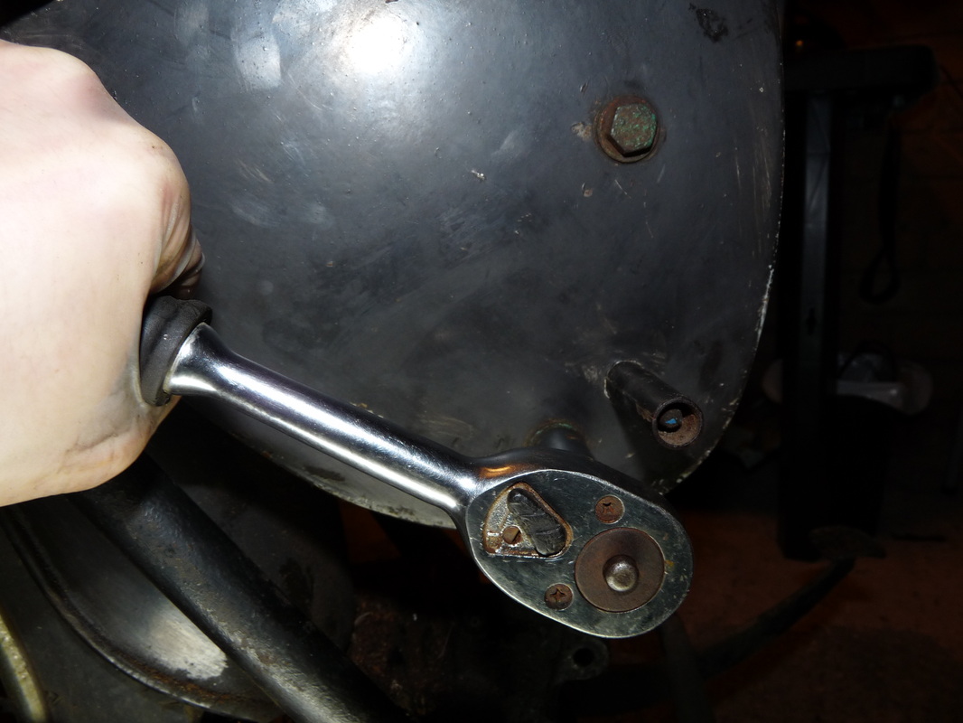
Undo the two bolts that connect the tool box parting to the frame using a 13mm socket "SAE size 17/32). Make sure you do not loose the spacers that are on the other side of the partition panel. Don't forget to bag them!
Undo the two bolts that connect the tool box parting to the frame using a 13mm socket "SAE size 17/32). Make sure you do not loose the spacers that are on the other side of the partition panel. Don't forget to bag them!
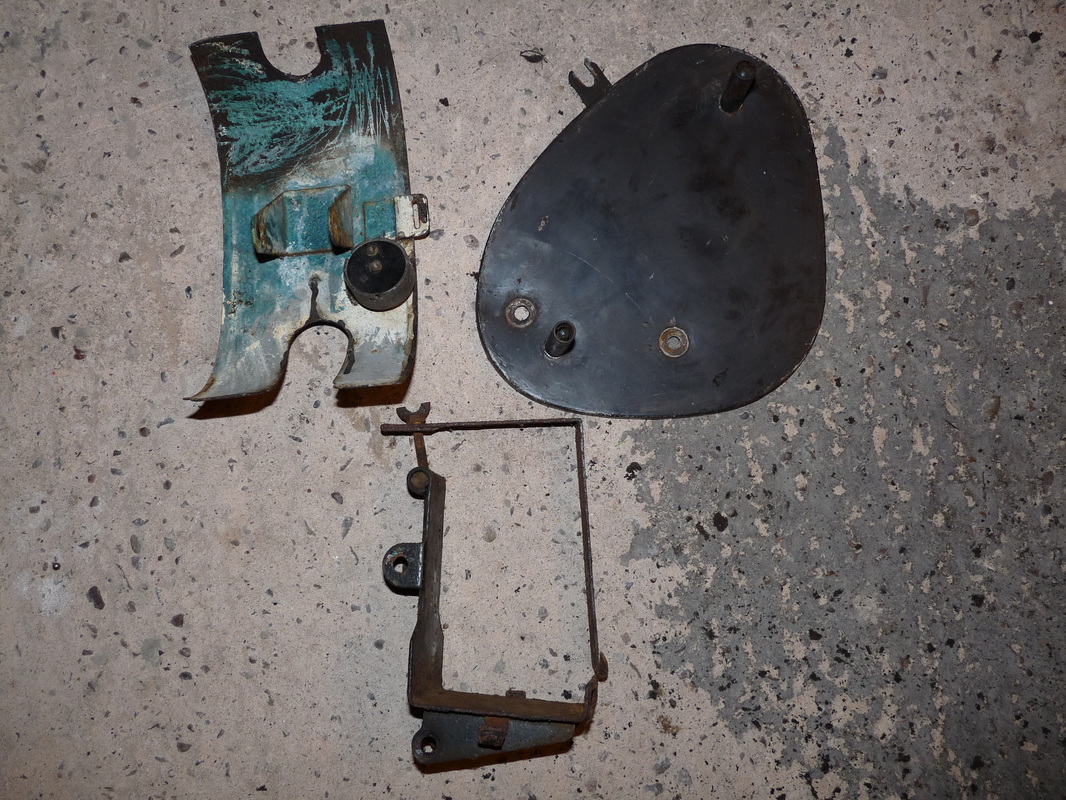
You should now be able to remove the front panel of the tool box and the battery bracket.
The partition panel will come off but you might have to give it a bit of a wiggle.
After scraping come of the muck off the front panel I can see green paint and signs of over spray from where someone has painted the bike black.
The partition panel will come off but you might have to give it a bit of a wiggle.
After scraping come of the muck off the front panel I can see green paint and signs of over spray from where someone has painted the bike black.
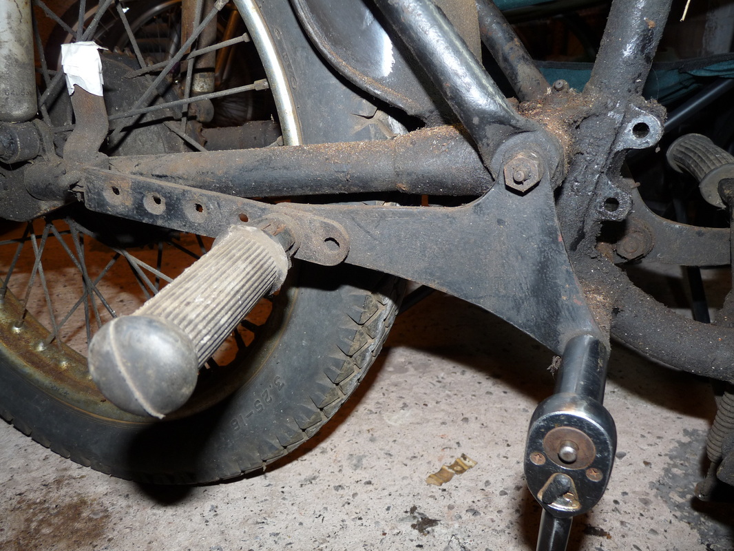
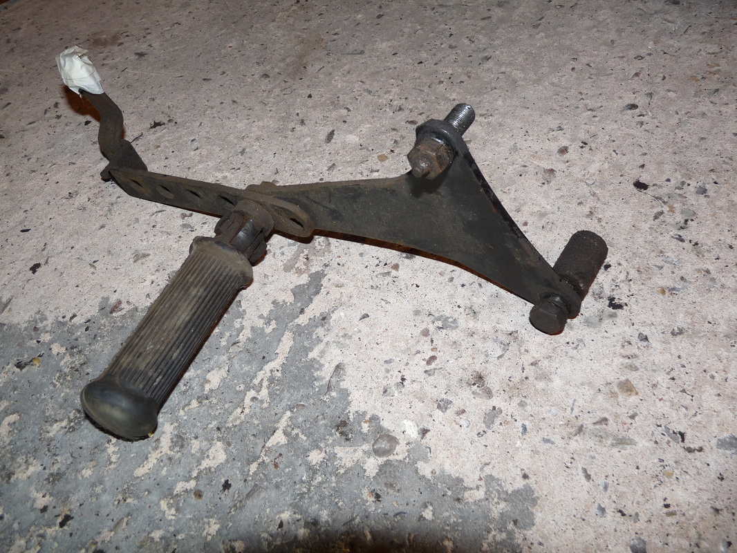
The last thing we are going to take of the frame here is the foot rest and exhaust bracket.
Simply undo the two bolts and it comes off. Make sure you don't loose the spacer though.
That's everything to be removed from the frame, time for another cup of tea.
Simply undo the two bolts and it comes off. Make sure you don't loose the spacer though.
That's everything to be removed from the frame, time for another cup of tea.